Self-Regulating Battery Charger Circuit
The post explains how a neat little self-regulating
automatic battery charger circuit can be made using just two inexpensive
transistors.
How it Works
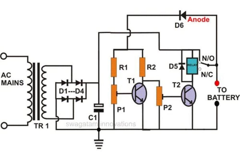
As can be seen in the diagram, this auto-regulating battery
charger circuit utilizes just two transistors for detecting the charging
thresholds, and cuts off the process as soon as these limits are detected.
Using two transistor actually makes the design hugely
sensitive compared to a single transistor charger circuit.
The indicated preset is set in such a way that the T1 is
just able to conduct at the specified full charge threshold of the battery.
When this happens T2 begins switching OFF, and ultimately at
a point it is unable to sustain the relay conduction and switches OFF the
relay, which in turn cuts of the input charging source with the connected
battery.
Conversely, when the battery voltage begins dropping, T1
gradually deprived of its adequate conduction voltage level, and ultimately it
ceases to conduct, which quickly prompts T2 to initiate its conduction and
trigger the relay into action,
The relay now reconnects the charging input supply with the
battery, and restores the charging process until it yet again reaches the full
charge threshold, when the regulating cycle repeats itself.
How to Sep Up the Circuit
Setting up this battery charger circuit for automatic
regulation is very simple and may be done in the following way:
• Initially,
do not connect the fixed transformer power supply; instead connect a 0-24V,
variable supply voltage to the circuit.
• Remove
the anode of D6 from the relay contact and connect it to the positive of the
power supply.
• Keep both
the presets somewhere at the center position.
• Switch ON
the power and adjust the voltage to 11.5 volts or lower.
• Adjust
P2, so that the relay just activates.
• Now
increase the volts to about 13.5 volts, and adjust P1 so that the relay just
deactivates.
The setting procedure of the circuit is now complete.
Check the whole procedure by continuously varying the
voltage up and down.
You may now remove the variable power supply and connect the
fixed transformer, bridge power supply to it.
DON’T FORGET TO RECONNECT THE ANODE OF D6 BACK TO THE RELAY
CONTACT OR THE BATTERY POSITIVE.
The battery connected to this circuit will be charged only
as long as its voltage is in between the above "window" level.
If the battery voltage crosses the above "window",
the relay will trip and stop the battery from charging.
Parts List
• R1, R2 =
10K,
• P1, P2 =
10K PRESET,
• T1, T2 =
BC 547B,
• C1 =
2200uF/25V
• C2 =
47uF/25V (Please connect this capacitor across the relay coil)
• D1---D4 =
1N5408,
• D5, D6 =
1N4007,
• RELAY =
12 VOLT, SPDT,
• TRANSFORMER
= AS PER THE CONNECTED BATTERY AH (DIVIDE BY 5)
The following diagram shows the instructions which needs to
be followed while setting-up the circuit with the desired cut-of thresholds,
using a variable power supply unit:

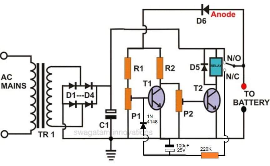
For One Shot Operation
If you want the above circuit to lock itself into a permanent cut off position when the battery is fully charged, then you may modify the design as shown below
Note: To ensure the relay does not latch itself quickly on
power switch ON, always connect the discharged battery first across the shown
terminals and then switch ON the input power.
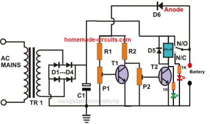
In order to indicate the charging status of the battery, we
can add a couple of LEDs to the above design, as shown below.
For the original post : CLICK HERE


Comments
Post a Comment